..หลังจากห่างหายไปนานก็กลับมาแจกต่อ แจกวงจรไฟฟ้าทั่วไป ไปจนถึงขั้นสูง มีวิธีต่อพร้อมทั้งบอกพิกัดอุปกรณ์ในส่วนต่างๆ เก็บไว้คนเดียวไม่มีประโยชน์อะไร เลยเอามาแบ่งกันเพื่อผู้สนใจนำไปต่อยอดเป็นไอเดียร์กันได้ครับ แต่ละกระทู้ผมจะลงทีละ 10 วงจร เพื่อไม่ให้กระทู้ยาวเกินไป แต่จะลงเรื่อยๆ ครับ
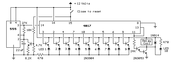
21.วงจร 9 วินาทีและควบคุมรีเลย์
วงจร 9 วินาทีและควบคุมรีเลย์
วงจรจะนับไปทีละวินาทีจนถึงขา IC =11 ลอจิก 1 ทรานซิสเตอร์นำกระแส ควบคุมรีเลย์
22.วงจร 32 พอร์ทจาก PC
วงจร 32 พอร์ทจาก PC
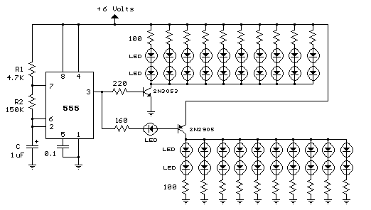
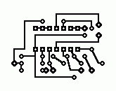
- วงจร 40 LED ไฟจักรยาน PCB
วงจร 40 LED ไฟจักรยาน PCB
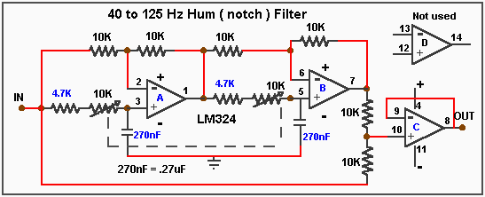
24.วงจร 45 to 125 Hz Hum (notch) Filter PCB
วงจร 45 to 125 Hz Hum (notch) Filter PCB
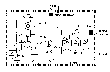
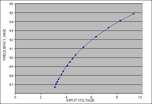
25.วงจร 90 MHz VFO สำหรับ Frequency Modulation
วงจร 90 MHz VFO สำหรับ Frequency Modulation
26.วงจรกราฟฟิกอีคลอไลเซอร์(6แบนด์) PCB
#วงจรกราฟฟิกอีคลอไลเซอร์(6แบนด์) PCB
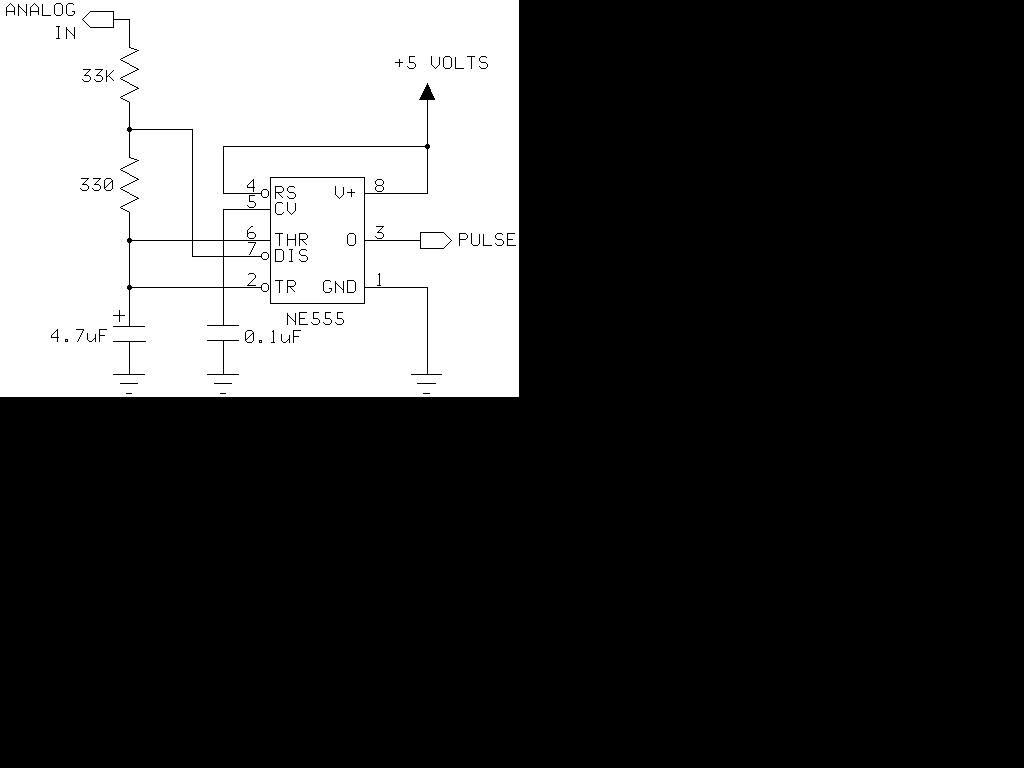
27.วงจร 555 Timer As An A-D Converter
วงจร 555 Timer As An A-D Converter
รายละเอียด
555 Timer as an A/D converter
I had a Basic Stamp project that needed to measure a nominal 12 volt battery, and I wanted a simple solution. This is the simplest I could come up with. The 555 timer will put out positive pulses. The pulse width is inversely proportional to the difference in voltage between the voltage at “ANALOG IN” and the voltage of the 4.7uF capacitor(let’s say 2.5 volts). To calibrate this circuit, hook it up to a Basic Stamp measuring positive pulses, and give the circuit a known voltage. Let’s say you get the number 2092 when you give the circuit 15 volts. Your coefficient is 2092 * (15 - 2.5) = 26150. Now you are ready to measure voltage with your Basic Stamp. Use the formula: voltage = 26150/pulse + 2.5 . You will have to modify this to work within the limits of the Basic Stamp’s math. The accuracy of this circuit rivals many digital voltmeters within the range I tested it (6 volts to 18 volts), about the same as a 10 bit A/D converter. The accuracy will shift with the processor clock and the +5 supply, so it is pretty good. Conversion time is under 1/10 second. Please note it will not measure voltages below 5 volts. Also, check the accuracy of your +5 volts. If it is 5.2 volts, you will need to use 2.6 in the formula. A sample program listing follows.
'uncomment the debug lines to get pulse value while calibrating
loop:
'debug cls
pulsin 0,1,w2 'I used pin 0
'debug w2
w1=26150 'This is the coefficient you will need to calibrate.
w4=w1/w2
w3=w4100 'I am going to get around the integer-only Stamp math.
w4=w2w4
w1=w1-w410 'remember the Stamp has left-to-right math
w4=w1/w2
w3=w410+w3
w4=w2w4
w1=w1-w410
w4=w1/w2
w3=w4+w3
w3=w3+250 '250 is really 2.5 volts
debug w3,“volts * 100” 'we get a reading in hundredths of volts
goto loop
28.วงจร A Strart-Up Delay for Vintage Amplifiers PCB
วงจร A Strart-Up Delay for Vintage Amplifiers PCB
ลาย PCB
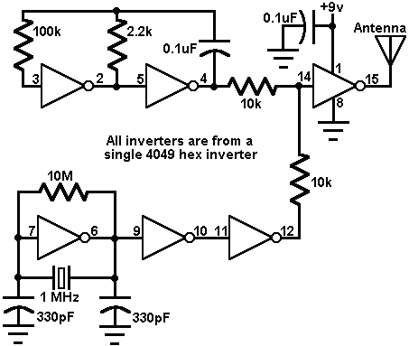
29.วงจร AM Tone Transmitter
วงจร AM Tone Transmitter
วงจรใช้ 4069 ทั้งหมด ส่วนด้านบนผลิตโทนในการส่ง ส่วนวงจรด้านล่างเป็นออสซิลเลเตอร์ ความถี่ 1 MHz จากนั้นรวมคลื่น AM ส่งออกอากาศ
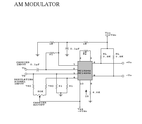
30.วงจร AM มอดูเลเตอร์
วงจร AM มอดูเลเตอร์
หากสมาชิกท่านใดต้องการเสริมความรู้ความเข้าใจเกี่ยวกับวงจรที่กล่าวมาก็สามารถคอมเม้นได้เลบครับ เผื่อเป็นไอเดียต่อยอดไปได้อีก
